
If you didn’t see my previous post on setting up an Arduino, then to catch you up, I’ve got a rowing machine, and I am trying to replace the basic LCD display on it with my own; to do this I need to read the sensor data it collects and process it myself.

Just so everyone is aware, this post could also be titled, “How I struggled with basic electronics” or “How you shouldn’t make assumptions when reverse engineering something”.
When I started this little project, I looked at the existing board that provides the LCD display for the rowing machine, and saw the two connectors. One for speed (which goes to the fan wheel at the front) and one for count (which goes to a sensor under the seat).

I made the assumption that because speed is an analog value, then the incoming data should be analog as well. This turned out to not be true, but first I’ll show you the wiring/code that told me it was not true.
Wiring
The connector for the speed sensor is actually a 3.5mm mono female jack:

So, I got a cheap 3.5mm cable, cut the end off it, then wired it to a junction.

I was momentarily confused by the fact there were 3 cables rather than 2 for a mono connector, but it turned out that the yellow wire was wired straight to the red, so I just ignored that one.
Reading an Analog Value
I thought that the speed sensor might be some sort of variable resistor, so that as the speed increased, the voltage allowed through the connection would increase.
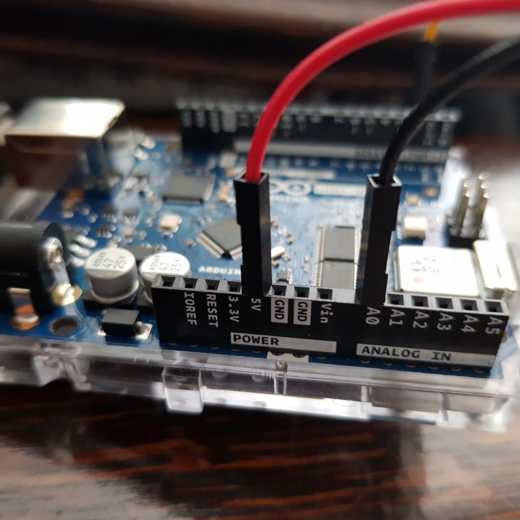
So to start with, I connected the 5V line on the Arduino to the red wire on the junction, and the black wire (GND) to the A0 analog input pin on the Arduino:
Then, I wrote some code to read the analog value (in volts) and write it to the Serial connector:
| void setup() | |
| { | |
| // Initialise my serial port with 9600 baud | |
| Serial.begin(9600); | |
| } | |
| void loop() | |
| { | |
| // Analog values are read as integer values between 1 and 1023. | |
| // Each 1 is a fraction of 5V. So 0 = 0V, 1023 = 5V, and the scale | |
| // goes in-between. | |
| const float VOLTAGE_MULTIPLIER = (5.0 / 1023.0); | |
| // Read the analog value on pin A0 (as fractions of 5V). | |
| int sensorValue = analogRead(A0); | |
| // Convert to volts using our multiplier. | |
| float sensorVoltage = sensorValue * VOLTAGE_MULTIPLIER; | |
| // Write the current voltage to the Serial port. | |
| Serial.println(sensorVoltage); | |
| } |
Before you connect the sensor, you just get analog ‘noise’ because there’s nothing connected to the A0 pin:

Once I connected the 3.5mm jack to the rowing machine’s speed sensor I got:

So that already tells me that the circuit is complete, and I’m seeing the 5V from the Arduino coming back.
When I pull on the rowing machine, my numbers change, but only very slightly (and not really in a way that relates to the speed):

I was definitely expecting more change in values from this; and as soon as the wheel of the rower starts to slow down, the number goes back to 5V.
What’s going on here? It doesn’t so much look like the voltage is changing with speed, it’s more like something is slightly interfering with a stable voltage reading…given the nature of the analog value sampling, it stands to reason that a switch rapidly changing from on to off and back might look like this…
Using a switch to read speed
So how can you use a switch to read speed? Well, I suspect there is a magnetic reed switch inside the wheel of the rowing machine, with a magnet attached to one of the blades of the fan inside the wheel.
Each time the magnet passes the switch, it will cause the circuit to break temporarily. The faster the blades spin, the more often the circuit will break.
To detect this, I need to change my approach a bit, and rather than read analog values, I need to read a digital value.
In order to get this working I had to sort out some basic electronics; I used the guide found here, which gave me the circuit I needed to make it work. It’s not too complicated to wire up, here’s the final diagram:
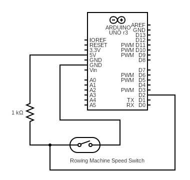
It looks much less neat than that on the breadboard, but here it is:

Then, I added the following code, to sample the digital input and watch for transitions.
| const int SPEEDPIN = 2; | |
| // Sample every 500ms | |
| const int SAMPLEFREQ = 500; | |
| // Variables for storing state. | |
| int switchState = 0; | |
| int lastSwitchState = 0; | |
| // Variable for remembering when we last sampled. | |
| unsigned long lastSampleMillis = 0; | |
| // Keep track of our transitions | |
| unsigned int transitionCount = 0; | |
| void setup() | |
| { | |
| Serial.begin(9600); | |
| } | |
| void loop() | |
| { | |
| // Each loop, read the state of the pin. | |
| switchState = digitalRead(SPEEDPIN); | |
| // When we transition from HIGH to LOW, the circuit has been broken | |
| if(lastSwitchState == HIGH && switchState == LOW) | |
| { | |
| // Increment our count of transitions. | |
| transitionCount++; | |
| } | |
| lastSwitchState = switchState; | |
| if(millis() - lastSampleMillis > SAMPLEFREQ) | |
| { | |
| // Once per SAMPLEFREQ milliseconds, determine the | |
| // speed (in terms of transitions per second). | |
| int speed = transitionCount * (1000 / SAMPLEFREQ); | |
| // Print out the speed of the sample | |
| Serial.println(speed); | |
| // Reset the count ready for the next sample. | |
| transitionCount = 0; | |
| lastSampleMillis = millis(); | |
| } | |
| } |
Now, when I plug this into the rowing machine and I give it a good couple of pulls, I get some meaningful speed readings out that correlate with how hard I pull it!

Next post will cover getting the data off the Arduino; connecting up the WiFi on my board and sending an HTTP request with my speed data!

3 replies on “Modding my Rowing Machine with an Arduino – Part 2 – Reading the Speed Sensor”
Hi, did you get any further with this project ?
LikeLike
Hi, yeah I did, the next post is at https://alistairevans.co.uk/2019/05/27/streaming-real-time-sensor-data-to-an-asp-net-core-app-from-an-arduino/. You can view all the rowing machine posts under the ‘rowingmachine’ tag: https://alistairevans.co.uk/tag/rowingmachine/
LikeLike
[…] my previous posts on Modding My Rowing Machine, I wired up an Arduino to my rowing machine, and streamed the speed sensor data to an ASP.NET core […]
LikeLike